Tuesday 29 November 2016

Electronics of bacteria's holiday home

The design of fuel cells' automation hardware is now complete and available from GitHub repository. The automation both monitors and takes care of the fuel cell and bacteria inside. A model device has been constructed as far as is possible until the missing parts are received.

Bacteria's holiday home automation


Regarding instrumentation, the following quantities are measured:
  1. Voltage between fuel cell terminals
  2. Current passing through the load
  3. Cathode liquid temperature
  4. Ambient light level
  5. Cathode liquid opacity
The choice of quantities was trade off between what is easy to measure and what is believed to affect performance.

Regarding care of the fuel cell, anode is cared for by pumping air through water with the aim of oxidizing water. Cathode liquid is slightly mixed by pumping the liquid around. To avoid pumps from clogging, a peristaltic pump is used.

The instrumentation part was already used for electrical measurements. The results of these were published in an earlier post. Light and opacity sensors have been built and tested, but have not seen real use yet. Temperature measurement is still missing since we have not received the sensor component yet.

Testing opacity sensor
Both air and cathode liquid pump have been tested to work, with the reservation that the test was conducted using a different pump model than the pump that will actually be used. Both work fine.


Wednesday 23 November 2016

First ideas and tests on ''Horses eyes''

Sensors are needed for two reasons. For providing horses interaction with the outside world and for safety purposes.

We started with two types of sensors. Ultrasonic Range Finder HC-SR04 (datasheet) and infrared HC-SR501 (datasheet and some additional interesting paper).

For the test purposes we made basic Ardino code for each sensor.

Ultrasonic HC-SR04

LED 13 turns on when object under 1m distance is detected. Each measurement is displayed on Serial Monitor. There is also 1s delay in order to make measurements readable.

#define TRIGGER_PIN  12  // Arduino pin tied to trigger pin on the ultrasonic sensor.
#define ECHO_PIN     11  // Arduino pin tied to echo pin on the ultrasonic sensor.
#define LED_PIN 13 // LED indicator of action.

int MAX_DISTANCE = 400; // Maximum distance we want to ping for (in centimeters). Maximum sensor distance is rated at 400-500cm.
int ACTION_DISTANCE = 100; // Distance where "Horse" takes action (in centimeters).
int  DISTANCE = 0;
void setup() {

  Serial.begin (9600);

  pinMode(TRIGGER_PIN, OUTPUT);
  pinMode(LED_PIN, OUTPUT);

  pinMode(ECHO_PIN, INPUT);

  MAX_DISTANCE = MAX_DISTANCE * 2 * 29.1; // Turn MAX_DISTANCE from CM into "TIME".
  ACTION_DISTANCE = ACTION_DISTANCE * 2 * 29.1; // Turn ACTION_DISTANCE from CM into "TIME".
}

void loop() {

  DISTANCE = dist_measure();

  if (DISTANCE < ACTION_DISTANCE) { // "Horse" takes action
    digitalWrite(LED_PIN, HIGH);
  }
  else {
    digitalWrite(LED_PIN, LOW);
  }

  Serial.println(DISTANCE / 58.2);
  delay(1000);
}

////////////////////////////////////////////////////////
int dist_measure() {
  unsigned long duration;

  // "Triggering" measurement
  digitalWrite(TRIGGER_PIN, HIGH);
  delayMicroseconds(20);
  digitalWrite(TRIGGER_PIN, LOW);

  // "Reciving" echo
  DISTANCE = pulseIn(ECHO_PIN, HIGH, MAX_DISTANCE);
  if (DISTANCE == 0) {
    DISTANCE  = MAX_DISTANCE;
  }
  return DISTANCE;
}


First tests shows us that the range of sensor is relatively limited, since the angle of its vision is only 15° on each side. Sound absorbing materials (thick clothes) are affecting on measurements accuracy.

To extend the vision angle we are considering to connect more than one sensor together with diode OR logic circuit.

Photo taken from: https://en.wikipedia.org/wiki/Diode_logic

Infrared HC-SR501

LED 13 turns on when object is detected. Detection of object is displayed on Serial Monitor in binary value. Again 1s delay is inserted in order to make measurements readable.

 #define TRIGGER_PIN 12 // Arduino pin tied to trigger pin on the IR sensor.  
 #define LED_PIN 13 // LED indicator of action.  
 int ACTION = LOW; // Should "Horse" take action.  
 void setup() {  
  Serial.begin (9600);  
  pinMode(TRIGGER_PIN, INPUT);  
  pinMode(LED_PIN, OUTPUT);  
  digitalWrite(LED_PIN, LOW);  
 }  
 void loop() {  
  ACTION = digitalRead(TRIGGER_PIN);  
  Serial.println(ACTION);  
  digitalWrite(LED_PIN, ACTION);  
  delay(1000);  
 }  

This sensor can sense (warm bodies) motion so it can be used to detect people, however it is useless for detecting walls or furniture. Range of sensor seems to be ok.


Conclusion

So far we are satisfied with the results. Since two types of sensors have different characteristics we believe that combined together we can get best sense of vision for the horse. Nevertheless we still have to discuss and test different solutions and decide where the sensors will be set.

Sunday 20 November 2016

Fuel cell electrical properties tests

Test setup

Tests were performed using Parmova fuel cell experiments on 2016-11-18. Voltage and current were measured using measurement device revision 1. Various sanity checks were performed by simultaneously using a multimeter and cross-comparing its readings with readings from the measurement device. Acquired readings were processed with LibreOffice Calc for visual display as charts.

Objective of the tests was more detailed evaluation of fuel cell performance with the secondary objective of testing the measurement device. There was no detailed test plan, new experiments were performed on ad hoc basis depending on results of the preceding tests. This exploratory testing method lead to main focus going to investigating the capacitive nature of the fuel cells, together with estimates of sustainable power production from a single cell.

Load resistor used was rated 4.7 kΩ.

Measurement interval is different in different tests, and regrettably was not recorded. This means that results from different tests are not directly comparable.

Results summary

The relatively high voltage measurements acquired in earlier tests using only multimeter voltage measurement turned out to be inaccurate in the sense that the results depend heavily on the connected load. Even the modest test load of 4.7 kΩ was enough to cause voltage collapse to sub 100 mV region.

Calculations of power output suggest that the sustainable rate is in the 1 μW region. This very low value poses a problem for actually using the power for anything meaningful. Increasing the output should be given some priority.

Measurement device performed well regarding voltage output, calculated voltages being in line with multimeter readings. The maximum measurable voltage value is quite low, however. It should be increased to cover value of 700 mv at least. For current, the recorded values were very close to lower limit, making it difficult to draw conclusions. If such low values need to be recorded, the device should be adapted to measure them in more precise way.

Tests

First test

This was the first test, performed without yet realising the the capacitive effects are signigicant. The assumption was that voltage and power output will be constant during the measurment,

Measurement device was connected and measurement was started. It was observed that the voltage dropped significantly after adding a load. The conclusion was that the initial measurement above 600 mV was result of storing production of the fuel cell over extended period to capacitance in the fuel cell.


Discharge

To better measure the effect of draining the stored energy, measurement was started before connecting the fuel cell to the measurement device.

Completely straight voltage in the start is caused by actual voltage value (> 700 mV) going above the measurement device's maximum of 270 mV.


Recharge

Behavior of fuel cell recharging after use was measured by first connecting the cell to load for extended period of time, then starting measurement and disconnecting the load.


Recharge and dischage

Test started with fuel cell emptied by extended connection with the load. With measurement ongoing, load was first disconnect for a period of time, then reconnected. This way both recharge and discharge was captured in a single continuous recording.


Recharge and discharge with current

The same test setup as Recharge and dischange was used, with the exception that current measurement was also connected.

Results of current measurement seem quite unusable, since the values are so close to zero that the device cannot properly distinguish changes.


Raw data

Raw data from the experiments is available here.

Thursday 17 November 2016

Measuring of bacteria activity

Otto and Martin made the circuit for measurement of voltage and current for each individual MFC's. Tests are currently undergoing night life measurements

 scheme
prototype


Tuesday 15 November 2016

Otto, Martin & Z's meeting: Horse power senses


On a meeting we have discussed work on HP bioreactor and horses senses

bioreactor can have different measuring devices (inputs):
Voltage (osciloscope) and current, temperature (acidity?) - shown on graphic LCD display, saved to computer (Rasbery PI?)

Additional hardware are two pumps - one for mixing of the meat mixture and other for oxidizing of the water

Output - might be small horses


moving horse
senses (inputs): 
- distance
- touch
- hp bioreactor inputs

program (AI)

outputs
movement


Saturday 5 November 2016

Horse movement - example 3: mechanical horses

There are different examples of mechanical horses in this post. Their aperance and movement (except for the first video) is surprising, although it is not related to their movement on the ground. These examples of mechanical horses may as well be construction of giant puppets (like marionettes or like in first example with the Warhorse) - puppets and automatons share their common history.


last: http://makezine.com/2015/10/08/mechanical-kinetic-horse-sculpture/ and artist Adrian Landon's Internet Site

link


Mechanical horses are like mechanical bulls toys for adults - but here is one great health project with mechanical (actually it is cybernetic) horse


Thursday 3 November 2016

Horse movement - example 2: Theo Jansen mechanism

simple design
a modified ratio of linkage and building of a wooden model (mainly for orientation about size)

basic trivia from WIKI: Theo Jansen (1948) is a Dutch artist. In 1990, he began building large mechanisms out of yellow plastic tubes (PVC) that are able to move on their own, known only as Strandbeest. The kinetic sculptures appear to walk. His animated works are intended to be a fusion of art and engineering, and he has said that "The walls between art and engineering exist only in our minds." He strives to equip his creations with their own artificial intelligence so they can avoid obstacles such as the sea by changing course when one is detected.

main page: http://www.strandbeest.com/
http://www.strandbeest.com/beests_leg.php
__________________________________

blog with a collection of content related to Jansen linkage (similar to this post here) - creator of this blog Joe Klan has also invented his own linkage which animate movement similar to spider. So blog is: mechanical spider


Jansen's linkage

From Wikipedia, the free encyclopedia

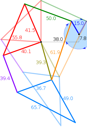
Theo Jansen's linkage. When the blue line at the right end of the picture is driven in a clockwise rotary motion, the leg (blue triangle at the bottom) executes a walking motion. Relative (dimensionless) proportions shown.
Jansens' Strandbeest
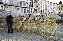
Theo Jansen's kinetic sculpture Strandbeest. A wind-driven walking machine.
The Jansen's linkage is a leg mechanism designed by the kinetic sculptor Theo Jansen to simulate a smooth walking motion[1] Jansen has used his mechanism in a variety of kinetic sculptures which are known as Strandbeests. Jansen's linkage bears artistic as well as mechanical merit for its simulation of organic walking motion using a simple rotary input.[2] Jansen's linkage is a robotic platform based on Theo Jansen's natural gearing mechanism. This work is focused in the design and development of the low cost robotic platform. The components used are readily available and inexpensive which makes it easy to build

Illustrations[edit]

Leg mechanism

From Wikipedia, the free encyclopedia
leg mechanism (walking mechanism) is an assembly of links and joints (a linkage) intended to simulate the walking motion of humans or animals. Mechanical legs can have one or more actuators, and can perform simple planar or complex motion.
Compared to a wheel, a leg mechanism is potentially better fitted to uneven terrain, as it can step over obstacles.[1]

Design goals[edit]

  • vertical speed as constant as possible while touching the ground (support phase)[1][2]
  • while the foot is not touching the ground, it should move as fast as possible
  • constant torque/force input (or at least no extreme spikes/changes)
  • stride height (enough for clearance, not too much to conserve energy)
  • the foot has to touch the ground for at least half of the cycle for a two/four leg mechanism[1] or respectively, a third of the cycle for a three/six leg mechanism
  • minimized moving mass
  • vertical center of mass always inside the base of support[1]
  • the speed of each leg or group of legs should be separately controllable for steering[2]
  • the leg mechanism should allow forward and backward walking[2]
Another design goal can be, that stride height and length etc. can be controlled by the operator.[2] This can relatively easily be achieved with a hydraulic leg mechanism, but is not practicable with a crank-based leg mechanism.[2]
The optimization has to be done for the whole vehicle – ideally the force/torque variation during a rotation should cancel each other out.[1]

History[edit]

Richard Lovell Edgeworth tried in 1770 to construct a machine he called a "Wooden Horse", but was not successful.[3][4]
The Plantigrade Machine by Pafnuty Chebyshev was shown at the Exposition Universelle (1878).

Gallery[edit]

Stationary[edit]

Walking[edit]

*4 legs6 legs
StrandbeestStrandbeest walking with four legs.gifStrandbeest walking with six legs.gif
GhassaeiGhassaei Beest Walking Paths traced.gifGhassaei Beest walking with six legs.gif
Klann linkage 1Klann Linkage Walking with four legs.gifKlann Linkage six legs.gif
Klann linkage 2Klann Linkage Walking with four legs - alternative measures.gif
Plantigrade MechanismPlantigrade walking 4 legs.gif

Complex mechanism[edit]

Shown above are only planar mechanisms, but there are also more complex mechanism:


- links on examples


TAKE ME U
more literature: